Most of us have already been there. You had a long and productive day and now it is time to have a good rest. You go on a light switch hunt, because it inconveniently went on a night stroll again and *BAM!*, your pinky toe decided to remind you that its only reason of existence is to let you FEEL its existence. Next thing you know a war breaks out, every volcano on earth erupts at once and our planet flies straight to the center of the sun. All of this because a light switch didn’t do its job properly. We cannot waste another second - let us join forces in a rebellion against the source of all evil!
If you have the exact same thought in mind as me or fight for an even greater cause, you are at the right place. Controlling home devices using relay modules is fairly quickly built up. We only need a few hardware components which don’t take too long to assemble and the code to control our system is a handful of Python lines.
Warning: You will be working with mains electricity which can seriously injure you. Please use extreme caution and if you’re not absolutely certain, ask someone who is. Saving one or two questions isn’t worth endangering your life.
Overview
In the previous posts we have been implementing Google Assistant on a Raspberry Pi and use it to run shell commands using our voice. I will use that setup to switch different devices with voice commands but naturally you will be able to execute the Python script any way you want. This post only covers the hardware installation with the relay module up to the execution of the controlling script. If you want to know how to run the script with your voice, please refer to my previous guide.
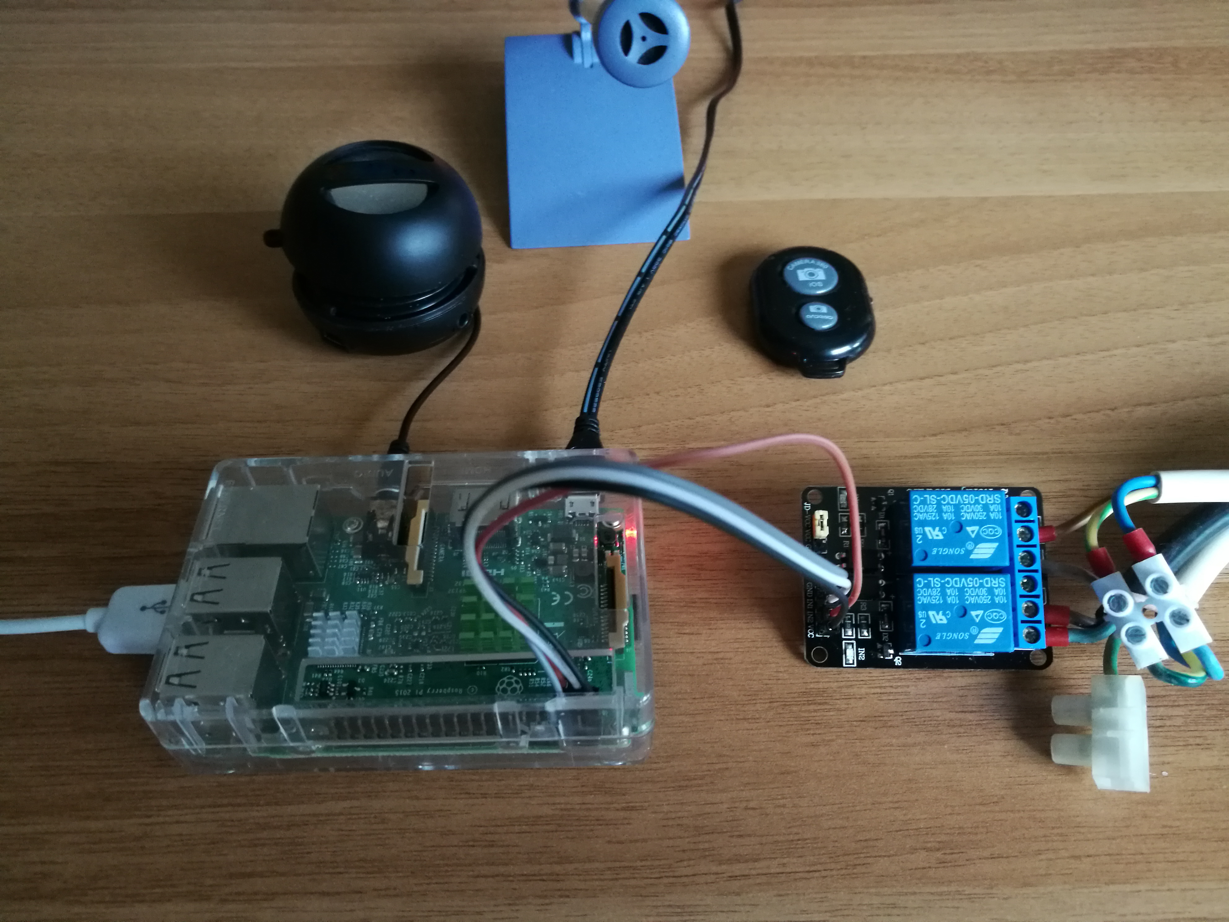
For this project you need:
- a Raspberry Pi or any other single-board computer with GPIOs containing a 5V pin
- a 5V relay module. The module I use it similar to this one and I have seen boards with 1/2/4/8/16 channels.
- Jumper wires (example). Depending on your single-board computer, you either need Female-Female or Male-Female wires.
- Voltage tester
Step 1: Wiring relay module with Raspberry Pi
Note: In this post I will use the American terminology for the switches. Refer to this page for their alternate names.
The relay modules we use will typically contain a mechanical metal switch which is controlled by an electromagnetic coil. Upon feeding power through the coil, the switch is moved to its alternate position. For the ceiling lights, we can use this three-way switch (SPDT) to keep the manual switches intact when adding the voice control feature. But this will heavily depend on how your lights switches have been wired up. Some will have the lights and switched directly connected to the mains, while others have a separate circuit for the switches and thus safer system for the installer. Either way, you should disconnect the power source by shutting off the appropriate breaker or fuse in the fuse box. More on this later.
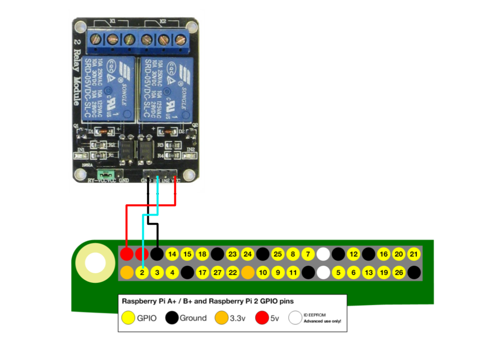
We will start off by connecting the relay module with the Raspberry Pi. Locate the set of pins that contains a GND, VCC and a IN# pin for every channel on your module. We connect the GND pin with a ground pin and the VCC with a 5V pin on the Raspberry Pi. Then connect a GPIO pin from the RasPi to the input pin of the channel you want to control. E.g. I used the GPIO2 pin to control the relay on channel 1, like so:
Step 2: Connect with target device
Next, we hook up the device we intend to control to the relay. Wiring with ceiling lamps is a bit tricky, so we will use a simple power strip for now. If you want to know how to connect your ceiling lights, refer to the appendix.
We will have to cut open the power strip wire, so ideally you want to use an old power strip which needs a “new haircut” anyway.
Cut the power strip cable into two parts. Depending on what type of cable you have, you will find three wires: Blue(Neutral), Brown(Live/Line/Hot), Green/Yellow(Earth/Ground). Remove approx. 1cm insulation from each of all six ends and twist the ends. Reconnect the Neutral and Earth wires with connector blocks and plug the Live wires into the relay block. It doesn’t really matter which sockets you use as long one wire goes into the middle socket:
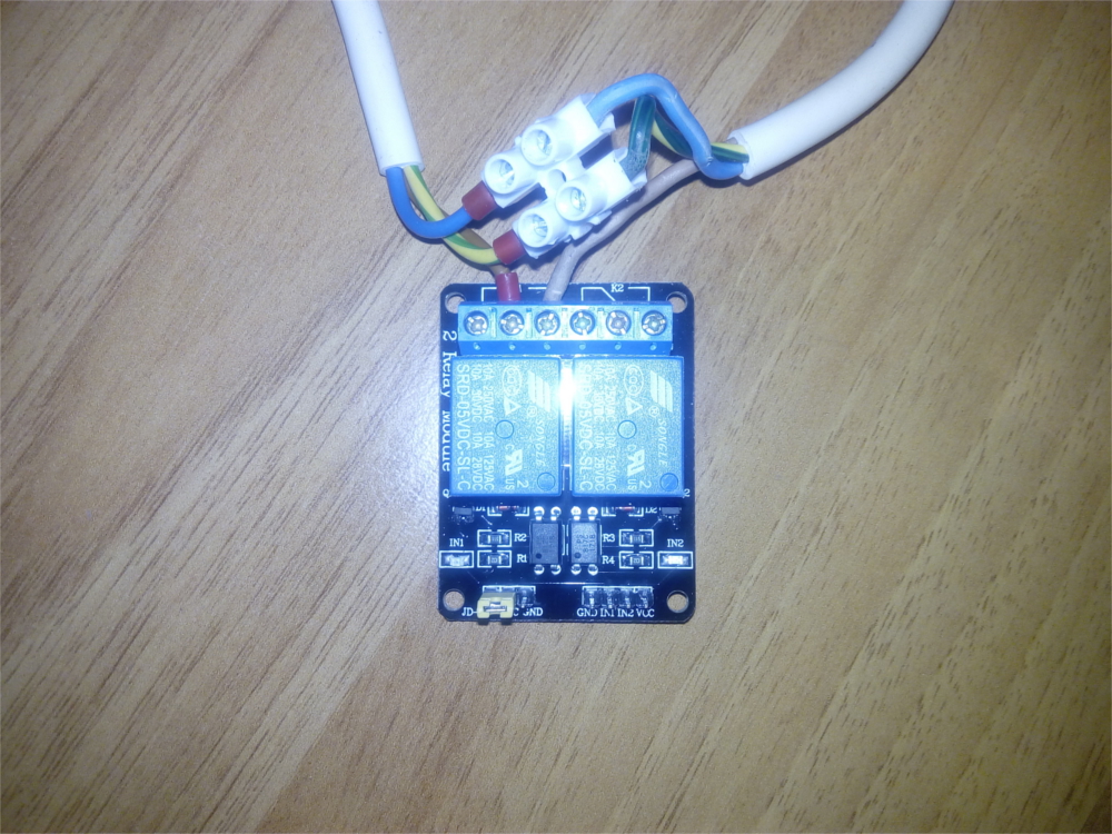
Make sure no wires are exposed at the joints. Best put the relay module in a small box.
Once everything looks tidy and ready, plug the power strip into the wall socket and your target device into the power strip.
Step 3: Operate relay with Python script
Time to peck some keys. Logged into your trusty Raspberry Pi and install RPi.GPIO if you don’t have it yet:
sudo apt-get update && sudo apt-get install python-rpi.gpio
If you are running Python 3, use:
sudo apt-get update && sudo apt-get install python3-rpi.gpio
Create a file in a location of your choosing and name it something like relay_on.py (although we don’t really have an “on” and “off” state, it’s simply two different states whose function will depend on how and what you plugged into the relay blocks). This file should contain the following:
import RPi.GPIO as GPIO

# refer to pins by the "Broadcom SOC channel" number
GPIO.setmode(GPIO.BCM)
# set GPIO2 to output
GPIO.setup(2, GPIO.OUT)
# set to False to turn on relay
GPIO.output(2, False)
Run the script with python relay_on.py to test your setup.
Change the number in GPIO.setup() and GPIO.output() of both scripts if you selected a different pin to control the relay channel. If your device still wont turn on, try changing the boolean value in GPIO.output() to True. This will depend on which relay sockets you chose.
Note: In Python you can choose between GPIO numbering (GPIO.BCM) and physical numbering (GPIO.BOARD). The first option uses the labels as the computer sees them while the latter counts the pins across as you see them. If you use this script on different Raspberry Pi models, you might want to the physical numbering system, which didn’t change over the different models.
Create a second file named e.g. relay_off.py which contains:
import RPi.GPIO as GPIO

# refer to pins by the "Broadcom SOC channel" number
GPIO.setmode(GPIO.BCM)
# set PIN 2 to output
GPIO.setup(2, GPIO.OUT)
# set to False to turn off lamp
GPIO.output(2, True)
# clean exit by resetting all ports used
GPIO.cleanup()
Change the values accordingly based on which pin(s) and relay sockets you chose.
If you can run [shell commands with your voice], you can now tell your digital assistant to run the Python scripts after specific voice commands. Smooth!
Appendix: Ceiling lights circuit
First we need to determine what kind of circuit you have within your walls, except if you wired everything yourself - but then again you probably wouldn’t read this part if you did.
There are a lot of ways to setup a lighting system. I will list the most common systems I encountered and write how to add our custom switch to it. When dismantling the light switch from the wall, you should be able to determine which system is installed in your room.
Warning: Remember to turn off the appropriate breaker or fuse in the fuse box before tinkering with the light switches.
Two-way switch
This is the simplest layout and unfortunately you wont be able to just add a custom switch while leaving the existing one operational (at least I wasn’t smart enough to come up with a solution). You either would have to replace the existing switch, which means if the voice switch fails, you wont be able to control the lights. Otherwise you could replace the two-way switch (SPST, single pole single throw) with a three-way switch (SPDT, single pole double throw) and run two wires between it and the relay block. The resulting circuit would look similar to the Figure 5 below, without SW2 & SW3 and e.g. SW4 replaced with the relay switch. The wire from the lamp would go into the relay’s middle socket while the two wires from the three-way switch in SW1 would go into the left & right socket.
Serial lighting circuit
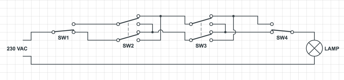
If you already have a circuit with multi-way switches in your room, we can reconstruct a four-way switch (DPDT, double pole double throw) with two relay blocks to get a component similar to SW2 and SW3. Plug each of the two wires coming from SW1 into the middle slots of separate relay blocks. The two wires from the next switch (e.g. SW2) go into the left and right slot of one relay channel. From the same slots you run two additional wires into the second relay channel but interchanged, i.e. left from the first into the right of the second and right of the first into the left of the second. As always, a picture is worth a thousand words:
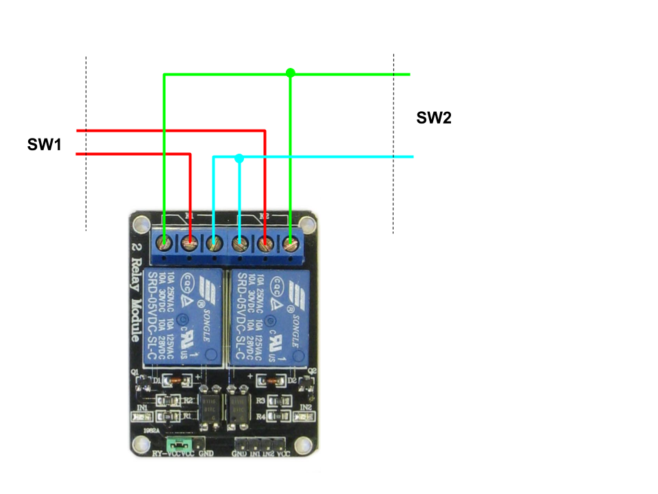
In the Python script, set both relays to the same boolean value at the same time to simulate a four-way switch.
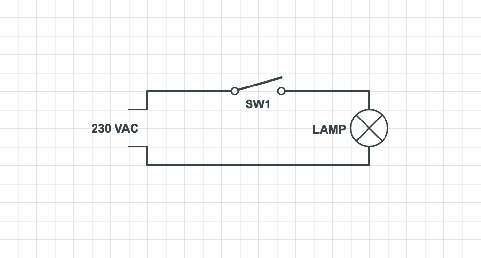
Parallel lighting circuit with relay unit
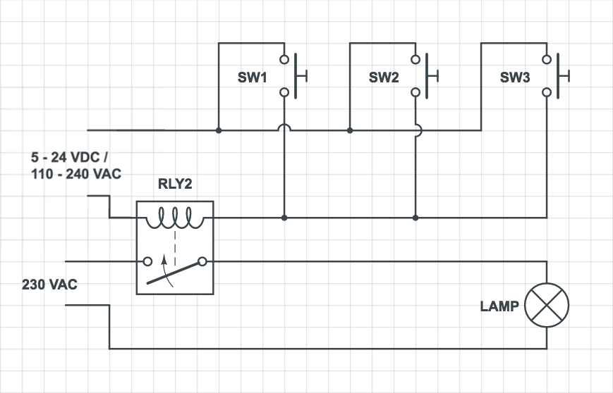
Note: The voltage values in the upper circuit are just an example. It could even have a higher value if you are working on an unusual system. Check if it is VAC first. If your multimeter says 0V, then it is probably VDC. The other way round is also applicable.
This one is fairly simple to set up. Every time the upper circuit is closed, a relay unit switches its state and opens or closes the lower circuit.
We install one relay block in parallel to one of the switches. One wire from each connector on the switch go the middle and an arbitrary side socket of the relay block.
To toggle the lights, you close the circuit once and open it after a short delay. Example Python script:
import RPi.GPIO as GPIO
import time

# refer to pins by the "Broadcom SOC channel" number
GPIO.setmode(GPIO.BCM)
# set GPIO2 to output
GPIO.setup(2, GPIO.OUT)
# close circuit
GPIO.output(2, False)
# small delay, otherwise relay wont register value change
time.sleep(0.5)
# reopen circuit
GPIO.output(2, True)
# clean exit
GPIO.cleanup()
This concludes the relay module implementation with single board computers. Have fun tinkering and always stay safe! I would love to hear about what you put together. See you next time!
Leave a Comment
Your email address will not be published. Required fields are marked *